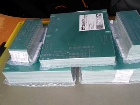
Skip to content

S8000 Harddisk

On powering up the Harddisk, the 24V level dropped to 20V and was also unstable.


After talking to other guys who have definitly more clue about PSUs, I changed the 3 load capacitors (4700µF/50V) and now the 24V supply is stable again.

The CDC FINCH handbook states that the BYTE_CLOCK signal should occur every 1.24µs and the INDEX signal should occur every 16.67ms. The BYTE_CLOCK gets low every time a byte passes the head, and the INDEX signal goes low every time the disk completed one revolution. The handbook states that in one revolution, 13,440 bytes are passed. 13,440 * 1.24µs (BYTE_CLOCK) = 16665.6µs = 16.67ms (INDEX).
16.67ms for one revolution, makes 59.99 revolutions per second, makes 3599.4 revolution per minute which matches the 3600RPM specified by the handbook as well.

To sum this up - this all makes sense.


Unfortunally, this is not the case for my FINCH. The BYTE_CLOCK signal occurs every 1.896µs. And the INDEX signal occures completly unpredictable.
I started tracing the Motor Board to find the optical switch which generates thr RPM signal. I found it and analyzed it with my logical analyzer. The motor of the harddisk has a disc on the back of the harddisk which runs through 3 optical switches. One is used for the RPM signal. The disc has an edge containing 4 valleys and 4 hills. So one revolution is made by having 4 low levels and 4 high levels passed. I measured 16.66ms which is kinda what I expected. Conclusion: The RPM of the disk as well as the RPM signal are both correct. On the harddisks mainboard, the RPM signal is exclusivly used by the intel D8749 microcontroller at pin 15 which is Bit 5 of its data bus. Right now, I have no clue what the D8749 does with this signal.

Harddisk aquired

Some time ago I was able to aquire a 24MB CDC FINCH harrdisk in a "brand new" condition on eBay from the US. It arrived without any obvious damages. I made the obligatory photos of the harddisk and its boards.

I also got lent a CDC FINCH Adapter board which I now retraced completly and additionally made a new circuit board layout to reproduce it.

Next steps will include to see if the harddisks powers up correctly and to check how further the S8000 selftest moves on with a harddisk attached. After that I'll go and reproduce the CDC FINCH Adapter-Board to send the original one back to its owner.

traced Stuff

  • when the S8000 CPU accesses the I/O Addresses 80xx to read or write the WDC registers, U16 and U17 are not enabled and Cp is HIGH too
  • The direction of U34 and U35 changes from time to time while the Selftest Routine of the S8000 CPU runs but with no obvious relation to it. Output enable stays the whole time high
  • The Dualport RAM is addressed for 0x8000 - 0x800F
  • For The Command Status register 0x8010, the dual port ram is not used.
  • When 0x8010 is accessed, O1 (Pin 14) of U3 goes low, Pin 6 of U5 goes low
  • Pin6 of U5 enables the Output of U20, U6, ...? and is an input pin of U30 (Pin 5)
  • So the status in 0x8010 is generated by multiple ICs on the board together - bit by bit.

Signals during WDC_TEST_ENTRY

The complete code of the traces below can be found here:

Procedure WDC_TEST_ENTRY in File p.testothr.s

What happens from the I/O point of view when my WDC is tested:

1.)
- To the WDC unit register 0x8001, 0xa5 is written.
- The WDC unit register 0x8001, is read back (0xa5)
- The data is compared if it is equal to the data which was written to it before.

This is done to check if there is a WDC present in the system.

2.)
- The WDC Command/Status register 0x8010 is read
- 0xf1 is read back
- 0xf1 is ANDed with 0x03 and then compared if it is equal with 0x03 (which is not the case, 0xF1 ANDed with 0x03 is 0x01 which is not equal with 0x03)
- If it would have been equal to 0x03, Error-Status 1001 whould have been reported.

3.)
- The WDC Command/Status register 0x8010 is read again
- 0xf1 is still read back
- It is now checked, that bit 8 is set which is the case for 0xf1

4.)
- To the WDC Command register 0x8000, 0x04 is now written

5.)
- The WDC Command/Status register 0x8010 is read again
- now, 0x71 is read back
- It is again checked, that bit 8 is set which is not the case for 0x71
- The WDC Command/Status register 0x8010 is now checked again up to 4000 times, but it keeps returning 0x71 for some time
- At some point, 0xf1 is read back

6.)
- The WDC Command/Status register 0x8010 is read again
- 0xf1 is read back
- it is checked, that bit 4 is set, which is not the case for 0xf1
- The WDC Command/Status register 0x8010 is now checked again up to 4000 times, but it keeps returning 0xf1 for some time
- At some point, 0xfd is read back

7.)
- The WDC Command/Status register 0x8010 is read again
- 0xfd is read back again
- it is checked that bit 2 is not set which is the case for 0xfd
- it is checked that bit 3 is not set which is not the case for 0xfd
- because of that, the test results now in an error and reports Errorcode 1002

Winchester Disk Emulator - first steps

Since I'm now done reconstructing the CPU Firmware, I did some very first steps building a Winchester Disk Emulator by recording the Firmware Self Test Routine regarding the WDC. The ASM code starts with:
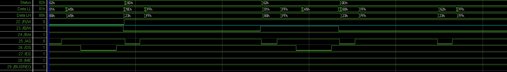
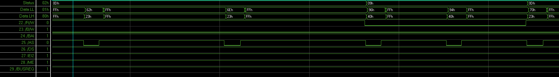
234a             21081000  ld      r8,#%1000
234e         4d0547460000  ld      %4746,#%0000
2354                 8811  xorb    rh1,rh1
2356             21078001  ld      r7,#%8001
235a                 cea5  ldb     rl6,#%a5
235c                 3e7e  outb    @r7,rl6
235e                 3c76  inb     rh6,@r7
2360                 8ae6  cpb     rh6,rl6
2362                 e605  jr      z,%236e
2364         4c0147480303  cpb     %4748,#%03
236a                 9e0e  ret     nz
236c                 e821  jr      %23b0
236e                 91f0  pushl   @r15,rr0
I've triggered on 0x8001 and Status (ST0-ST4) = 0x02 (= I/O reference, check Handbook 03-3237-04 page 4-8). In the following two screenshots you see the data writing to 0x8001 of 0xa5 (instruction 0x235c) as well as the data reading of 0x8001 (instruction 0x235e). You'll also notice, that on readback the higher 8 bit are 0xff. This is because the WDC has a dualport RAM which only stores 8 Bit of data and is attached to AD0-AD7. The 2nd screenshot shows following instructions from the above listed Assembler Code.


Logic Analyzer

My 45,- EUR LA from China arrived yesterday and I started to debug why one of my harddisks refuses to work with my AVR but works with an old MS-DOS system. I found out, that a 0x91 (Drive Initialization) command is needed to get the drive working. After Power-Cycling the drive while MS-DOS was running, I saw that on the next read request, MS-DOS also gets an error. But right after the error, MS-DOS issues a Recalibrate and a Initialize Drive Command and then successfully retries the read.
I now issue a Recalibrate and Initialize Drive Command during the Emulators Bootup process once and the drive is now fully functional.

WDC

When I'm not busy building the v2 Prototype of my P8000 WDC Emulator, I'm tracing the original S8000 WDC and create circuit diagrams. When this is done my next plans are to record a complete WDC-Hardwaretest-run with a Logic Analysator and shape the disassembled S8000-CPU Firmware in a way it can be re-assembled. The long-term objective is to build a WDC emulator for the S8000 since the CDC FINCH drives seem to be unobtainable.